Diy Gps Datalogger
Since a long time I wanted a GPS Datalogger, I do have a Garmin GPS, which to my dismay does not provide me with all the data that I need. I wanted the NMEA data from my GPS device, but as it turns out I cannot have it. So, I decided to build myself one, so that I can track my travel pattern and do some fun stuff. Before going down this path, I checked online for some cheap dataloggers but they were all in the range of $100 to $199, too much for my tiny hobby.
Following are the steps to build your own cheap GPS datalogger, I wrote these steps as a future reference to me and also for someone who would like to walk this path. A detailed component list is attached at the end of the article.
Step 1) Getting a cheap GPS Module:
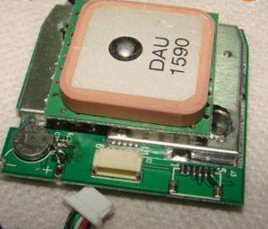
There are lots of GPS modules available in the market ranging from $50 to $200 which can do lots of fancy things, but do you need all those things ? for me the answer was no. So I went to eBay and brought a cheap GPS module based on SiRF 2 chip-set, it can track up to 12 GPS satellites as compared to 20 with other high-end GPS modules, but then you only need 4-5 GPS satellites at a given point in time to correctly identify your position. Here’s the GPS module that I brought for $14 and the eBay link
Step 2) RS232 to TTL conversion
Some GPS modules output TTL (Transistor Transistor Logic) signals and some output RS232 signals (mine used RS232), if you are planning to use the GPS module with a PC then RS232 is great, but in my case I wanted it to be used with Arduino and with a data logging circuit which logs raw data to a Micro SD card.
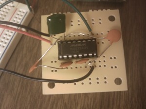
So, I had to build a circuit to convert RS232 signal to TTL signal. I used a well known IC, MAX 232A for conversion. To complete the circuit you need five 0.1 µF capacitors. Following is the pin layout of MAX 232A and a circuit diagram that I used to convert RS232 signal to TTL signal.
This is how the conversion circuit looks after hooking up all the components and IC.
Step 3) Designing a Voltage Regulator to use a 9V battery to power the circuitry
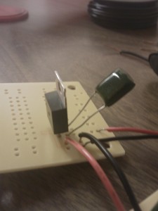
I am planning to use a 9V battery to power the entire unit. The GPS receiver needs 5V, so I needed to design a voltage regulator circuit with 5V constant output voltage. I used the LM7805 voltage regulator, it was cheap and easy. I used a 0.1 µF Capacitor at the output to prevent any spikes, but it’s optional to use and only LM7805 will do the job.
The circuit diagram for the Voltage regulator, in case you need, here
Step 4) Serial Data Logging Circuitry.
For logging the serial data output from the GPS, I used Open Log from Sparkfun. It logs serial data to a micro SD card, the baud rates can be adjusted. I had to adjust the baud rate to 4800 so as to match the GPS Data baud rate. It’s simple and extremely easy to use, I got it for $25.
Step 5) Assembly
Get everything soldered and make sure you do not have any open ends. I am not very good at soldering and suck in PCB optimization. Anyhow, I got my prototype working, its not the preetiest thing in the world but hey it works !
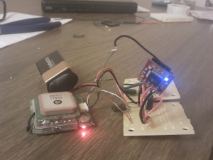
Since I was indoors I could not get a proper fix on the satellites. But, I did get valid GPS sentences logged.
$Baud rate: 4800  System clock: 12.277MHz
$HW Type: S2AM
$Asic Version: 0x23
$Clock Source: GPSCLK
$Internal Beacon: None
$GPGGA,235948.000,0000.0000,N,00000.0000,E,0,00,50.0,0.0,M,0.0,M,0.0,0000*77
$GPGSA,A,1,,,,,,,,,,,,,50.0,50.0,50.0*05
$GPRMC,235948.000,V,0000.0000,N,00000.0000,E,,,091102,,*1E
$GPGGA,235949.000,0000.0000,N,00000.0000,E,0,00,50.0,0.0,M,0.0,M,0.0,0000*76
$GPGSA,A,1,,,,,,,,,,,,,50.0,50.0,50.0*05
$GPRMC,235949.000,V,0000.0000,N,00000.0000,E,,,091102,,*1F
$GPGGA,235950.000,0000.0000,N,00000.0000,E,0,00,50.0,0.0,M,0.0,M,0.0,0000*7E
$GPGSA,A,1,,,,,,,,,,,,,50.0,50.0,50.0*05
$GPRMC,235950.000,V,0000.0000,N,00000.0000,E,,,091102,,*17
I used Google Maps to plot the graph of Altitude Vs Distance using a KML file, I am in a process of optimizing the code, currently I am a bit tied down and will upload the code once I get some free time.

The following graph shows Velocity Vs Distance, height of the graph is the velocity of my car, notice how the height of the graph decreases at the turns and at the stop lights. I had to do some math to calculate the distance between two consecutive coordinates to get the velocity, I will post the formula and the Java code that I used to calculate the velocity once I get some time. If you want to know more about calculating the distance refer to this post Calculating distance between 2 points on the Earth
Component List:
- A GPS Module
- Serial Data Logger (like Open Log from Sparkfun)
- MAX 232A IC
- Five 0.1 µF Capacitors
- LM7805 Voltage Regulator
- 9V Battery